Monday, July 4, 2011

NOT gates


The NOT gate has a single input and one output. 

The little bubble on the output indicates that the output goes LOW when the input goes HIGH. 

We can say that the output goes LOW when the input is ACTIVATED. 

The opposite happens when the input is LOW. The output goes HIGH. 

The TRUTH TABLE shows that the output is the opposite of the input. 

The NOT gate is also called an INVERTER. It inverts the input. 

The Boolean expression is A = Z 

Which is read as, NOT A EQUALS Z 

or IF A IS LOW THEN Z IS HIGH 

or BAR A = Z

AND Gates

The AND gate has two or more inputs and one output. 


The output voltage goes high only when all input voltages are high. 

In the switch diagram the lamp lights up only when A and B are operated. If only one is switched then the lamp stays off. 

In the truth table Z = 1 only when A and B = 1 

The Boolean expression is A. B = Z which translated says, A and B both high, makes Z high.

OR gates

The OR gate has two or more inputs and one output. 


The output voltage goes high only when one or more input voltages are high. 

In the switch diagram the lamp lights up when A OR B (or both) are operated. 

In the truth table Z = 1 when A or B = 1. 

The Boolean expression is A+B = Z which translated says, A or B high makes Z high. 

The plus sign + translates as OR.

Binary

In 1854, a central paper on binary systems was published by the mathematician George Boole. This paper laid out the groundwork for what would eventually be called Boolean algebra. With the advent of electronics, binary systems suddenly made incredible sense. Most electronic systems function on a switch-based system, with current either running or not running. In 1937, Claude Shannon set out the foundations for the theory of circuit design using binary arithmetic. In 1940, the age of binary computing began with the release of Bell Labs Complex Number Computer, which was able to perform extremely complex mathematical calculations using a binary system.

Binary numbers (1 or 0) represent on(1) or off(0).

Typically you work out binary like this: 

256 128 64 32 16 8 4 2 1

If you have say a decimal number of 254, to work out the binary code you would use the system above to work it out. So,

256 128 64 32 16 8 4 2 1

0 1 1 1 1 1 1 1 0

The number that was given (254) is equated in the system above if you were to add up the numbers that have 1s underneath them.From there you can learn to translate binary into decimal, decimal into hexidecimal (not using binary,because hex is a whole other language base) which then goes onto C++ programming and all the rest.

If you're working out bigger numbers, for instance 3813, then you need to create a bigger system in order to work out the binary code so therefore you need to do this:

2048 1024 512 256 128 64 32 16 8 4 2 1

1 1 1 0 1 1 1 0 0 1 0 1

So this is your Binary Code for 3813:

1 1 1 0 1 1 1 0 0 1 0 1

If you want to be lazy you can just use your calculator on your computer. You need to switch the view to scientific which calculates binary, decimal, hex and octal. I suggest you make sure you understand binary code first before moving onto hex because the development between them can become very confusing.

Hour Timer Circuit

These two circuits are multi-range timers offering periods of up to 24 hours and beyond. Both are essentially the same. The main difference is that when the time runs out, Version 1 energizes the relay and Version 2 de-energizes it. The first uses less power while the timer is running; and the second uses less power after the timer stops. Pick the one that best suits your application.


The Cmos 4060 is a 14 bit binary counter with a built in oscillator. The oscillator consists of the two inverters connected to Pins 9, 10 & 11; and its frequency is set by R3, R4 & C3. The green Led flashes while the oscillator is running: and the IC counts the number of oscillations. Although it's a 14 bit counter, not all of the bits are accessible. Those that can be reached are shown on the drawing.

By adjusting the frequency of the oscillator you can set the length of time it takes for any given output to go high. This output then switches the transistor; which in turn operates the relay. At the same time, D1 stops the count by disabling the oscillator. Ideally C3 should be non-polarized; but a regular electrolytic will work, provided it doesn't leak too badly in the reverse direction. Alternatively, you can simulate a non-polarized 10uF capacitor by connecting two 22uF capacitors back to back (as shown).

Using "Trial and Error" to set a long time period would be very tedious. A better solution is to use the Setup tables provided; and calculate the time required for Pin 7 to go high. The Setup tables on both schematics are interchangeable. They're just two different ways of expressing the same equation.

For example, if you want a period of 9 Hours, the Range table shows that you can use the output at Pin 2. You need Pin 2 to go high after 9 x 60 x 60 = 32 400 seconds. The Setup table tells you to divide this by 512; giving about 63 seconds. Adjust R4 so that the Yellow LED lights 63 seconds after power is applied. This will give an output at Pin 2 after about 9 Hours. A suitable Veroboard layout for each version is shown below:

Make Electronic Siren Circuit


The sound produced imitates the rise and fall of an American police siren. When first switched on the 10u capacitors is discharged and both transistors are off. When the push button switch is pressed to 10u capacitor will charge via the 22k resistor. This voltage is applied to the base of the BC108B which will turn on slowly. When the switch is released the capacitor will discharge via the 100k and 47k base resistors and the transistor will slowly turn off. The change in voltage alters the frequency of the siren. The oscillator action is more difficult to work out. As the BC108B transistor switches on its collector voltage falls and so the 2N3702 transistor is switched on. This happens very quickly ( less than 1us). The 22n capacitor will charge very quickly as well. As this capacitor is connected between the collector of the 2N3702 and the base of the BC108B, it soon reaches almost full supply voltage. The charging current for the capacitor is then much reduced and the collector emitter voltage of the 2N3072 is therefore increased; the collector potential will fall. This change in voltage is passed through the 22n capacitor to the base of the BC108B causing it to come out of saturation slightly. As this happens its collector voltage will rise and turn off the 2N3072 transistor more. This continues until both transistors are off. The 22n capacitor will then discharge via the 100k, 22k resistor, the closed push button switch, 9V battery, the speaker and 56 ohm resistor. The discharge time takes around 5-6msec. As soon as the 22n capacitor is discharged, the BC108B transistor will switch on again and the cycle repeats. The difference in voltage at the collector of the BC108B (caused by the charging 10u capacitor) causes the tone of the siren to change. As the 10u capacitor is charged, the tone of the siren will rise, and as it is discharged, it will fall. A 64 ohm loudspeaker may be used in place of the 8 ohm and 56 resistor, and the values of components may be altered to produce different sound effects.

SEVEN SEGMENT CIRCUIT


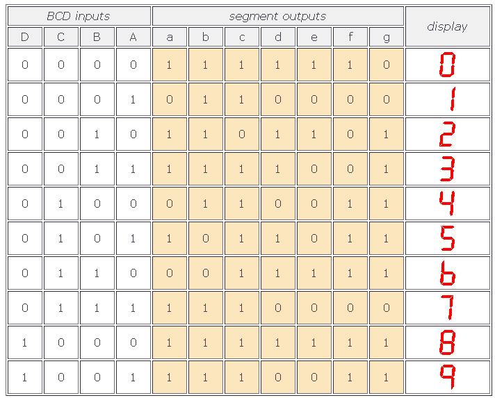
The IC 4511 is a BCD to 7-segment decoder driver. Its function is to convert the logic states at the outputs of a BCD, or binary coded decimal, counter like the 4510 into signals which will drive a 7-segment display. The display shows the decimal numbers 0-9 and is easily understood.


7-segment display


There are two important types of 7-segment LED display. In a common cathode display, the cathodes of all the LEDs are joined together and the individual segments are illuminated by HIGH voltages. In a common anode display, the anodes of all the LEDs are joined together and the individual segments are illuminated by connecting to a LOW voltage.

The 4511 is designed to drive a common cathode display and won't work with a common anode display. You need to check that you are using the right kind of display before you start building.

The 0.56 in. 7-segment display common cathode available from Rapid works well as part of a prototype board circuit.

When the 4511 is set up correctly, the outputs follow this truth table:


In normal operation, the lamp test and ripple blanking inputs are connected HIGH, and the enable (store) input is connected LOW. The circuit diagram shows the 4511 and a 7-segment common cathode display connected to the outputs of a 4510 BCD counter:

SEVEN SEGMENT CIRCUIT

To build this circuit follow the prototype board layout from the 4510 Beastie Zone web page and then add the 4511 with connections to a third prototype board, as shown below: 
SEVEN SEGMENT CIRCUIT